Joined: Jun 09, 2009 Posts: 132 Location: Honolulu HI
Audio files: 48
Posted: Wed Jan 25, 2012 2:51 am Post subject:
Just finished the circuit for my mono version of this. Will post the connections after I draw them up. Basics is that it's a 23 key keyboard (bottom C would've required either sacrificing several octaves of range or putting in way more extra circuitry than it would be worth. In case you're wondering why it's because you can't get a close enough division for it (c8 or c7, can't remember which) from 2mhz with the 4040) with a 4 position octave selector switch. Chips used are the 4046, 2 4040s, a 4051 and, currently, 1/6th of a 4069 (don't worry, I'll at least use the other ins for lfos and an always useful inverted square wave). Everything's pretty much straight-from-the-datasheet straight forward. Only really clever (alright, at least by my standards) thing I did was to split the reset pin output on the 4040 going to the keyboard switch array into a separate output for each octave, then take a lead from the lower octave and run it to the 4069 so that the voltage drop when a key is depressed (in that octave) triggers a high out on the 4069 which is routed to the A control of the 4051......ummmm...it'll probably make more sense in the drawing.
Playing will probably sound better after I glue my freshly cut lexan strips over the switches.
Wish I'd had the foresight to pick up some IC sockets today when I was getting my perfboard so that I could start transferring this to the perfboard.
Oh, also of note is that the plastic VHS case that the switches are glued to was found on the side of the road. The tape it contained had 80's porn on it. Thought you should know.
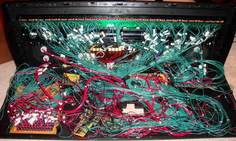
i finally got round to starting this project, thanks for the schematics Marco!! took about 11 hours to build the TOG board, now to work on wave shapers, EG, VCF and VCA per voice......
IMG_3977.jpg
Description:
Filesize:
3.3 MB
Viewed:
2813 Time(s)
This image has been reduced to fit the page. Click on it to enlarge.
good work! thats some rats nest!! to be fair mine will end up the same in all likelihood!
think i'm going to aim for an LM13700 hp/bp/lp vcf and vac for each note, but i need to work out a simple voltage controlled a/r envelope generator first.
i finally got round to starting this project, thanks for the schematics Marco!! took about 11 hours to build the TOG board, now to work on wave shapers, EG, VCF and VCA per voice......
Hello:
You will use this schematics for wave converter ?
If the answer is yes give me some time to upload the chart value (capacitors and resistors: C1, C2, R1).
Analog Custom - I was hoping to try your mk50240 emulation for my next top octave synth, but all the images are gone. Can you please repost them? You should be able to upload them directly to the forum instead of hosting on another site. _________________ JacobWatters.com
Hi:
Here the full access to all information, including files .pcb and "Protel PCB program" (old 1.5 version) to make changes on the pcb. Soon try to upload the information to this site.
Joined: Nov 10, 2011 Posts: 878 Location: Lancashire, England
Audio files: 14
Posted: Sat Jun 16, 2012 5:22 am Post subject:
sizone wrote:
Oh, also of note is that the plastic VHS case that the switches are glued to was found on the side of the road. The tape it contained had 80's porn on it. Thought you should know.
Ahahahaha oh thats just brilliant
Did you ever re-combobulate the schematics you mentioned one page back in the thread?
I'm doing something now which may require "top octave" methods ... _________________ As a mad scientist I am ruled by the dictum of science: "I could be wrong about this but lets find out"
If the answer is yes give me some time to upload the chart value (capacitors and resistors: C1, C2, R1).
@AnalogCustom:
thanks for the schematics, i'll give it a try.
instead of using an entire cd4024 to make only one division, you could also use a cd4027 and save some board space
a ba634 would save even more space
can you post the values for resistors and capacitors on the wave converter?
thanks
I did tests with 4 wave shaper (solina, crumar,..).
I'm curious as to what were the 4 waveshapes you tried, and which string synths they were based on? I'm amazed at the differences in tone that one hears across the various vintage string synth models. Some sound more like organs played through a chorus pedal, and others like an other-worldly lush string ensemble (I'm thinking of the Solina particularly). I feel like these differences in tone must have as much to do with the waveshapers as it does the chorus circuits--yes?
The PolyMoog is another one with an unbelievable, unmistakeable sound that I'm guessing has much to do with the waveshapers and fixed filters on the individual voices.
Id be all over it, if someone made a project available that mimicked the circuit path of one of these machines-- divide down, shapers and fixed filters, bbd ensemble.
Each step affects the final sound (wave shaper, ensemble-chorus, resonant filter, etc ...). Whaveshapes types:
Saw RC (nonlinear):
Crumar Multiman, Elka Rapsody, Roland VP330, etc...
If the answer is yes give me some time to upload the chart value (capacitors and resistors: C1, C2, R1).
@AnalogCustom:
thanks for the schematics, i'll give it a try.
instead of using an entire cd4024 to make only one division, you could also use a cd4027 and save some board space
a ba634 would save even more space
can you post the values for resistors and capacitors on the wave converter?
thanks
Hello:
I've had this project abandoned, but I am planning to retake these days. Please give me a few days to sort the information you ask. I will open a new topic called: "Full Polysynth Project").
You cannot post new topics in this forum You cannot reply to topics in this forum You cannot edit your posts in this forum You cannot delete your posts in this forum You cannot vote in polls in this forum You cannot attach files in this forum You can download files in this forum


 Forum index » DIY Hardware and Software


 FAQ
 Calendar
 Search
 Memberlist
 Usergroups
 Register
 Profile
 Log in to check your private messages
 Log in
 Chat Room


 took about 11 hours to build the TOG board, now to work on wave shapers, EG, VCF and VCA per voice......