Posted: Thu Oct 11, 2018 12:28 pm Post subject:
Low parts count zener-inductor waveshaper/modulator
Hi there, was messing around on the bench and stumbled on the schemo below. Output goes from a cheap distortion pedal sound to reasonably good balanced modulator effects depending on what you put in.
Stripboarded in about 5 minutes. this is like 8 parts, super super simple.
Anyone else have variations or know of this design in the wild. hard to believe it's new, but for me it was a complete accident. Then again I almost never use inductors for anything except power so new for me anyway.
I was going to do another blog entry with before and after WAV files, but doing scope shots as well is a great idea. I'll do that too. Thanks for the suggestion. _________________ Visit my AUDIODIWHY blog and website
Joined: Nov 29, 2008 Posts: 652 Location: Berlin by n8
Audio files: 23
Posted: Fri Oct 12, 2018 11:59 pm Post subject:
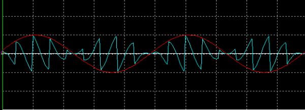
u could also just open the wav in a audioeditor and screenshot the waveforms there, but Scopies are somehow more elegant.
i understood that it is acting like a RM?
can u may run a test where u feed in the same sine in both signal and carrier in?
This is a special task for an RM, it acts then as a frequenzy-doubler, cos it is performing sin²
the other standard test would be sin&saw, the frequenzy of the one should be an uneven multiply of the other eg 1khz/3khz or 1khz/5khz 1/7 .....
this is to see how it is performig the phase inversion when the carrier is going thru zero, means that the saw is running backward then
Hi Gabi:
Not quite; I am saying that to my ears it can, sometimes, sound a bit like an RM.
I don't think this circuit could ever truly be an RM--you'd need at least 2 transformers for that right?
What I think is happening here is that any beat frequencies between the sine waves or whatever source material you feed in get emphasized by this simple circuit, causing things to sound "metallic" at times; maybe a bit like an RM in play when it's not.
If time permits I will post sound samples (including a few scope shots) in my blog. In the meantime, again, if anyone can turn me onto other zener/inductor based synth distortion units, I'd really like to see what real EE's (which means, not me!!) have come up with.
Thanks. _________________ Visit my AUDIODIWHY blog and website
Joined: Jan 14, 2010 Posts: 6058 Location: Moon Base
Audio files: 728
Posted: Mon Oct 15, 2018 4:42 am Post subject:
just a quick note: I am not so sure if that zenerdiode across the inputs is such a great idea, as it pretty much
shorts them when the voltage on input 2 is lower than the voltage on input 1. _________________ "My perf, it's full of holes!" SoundCloudBandCampMixCloudTwitchYouTube The Golden Shrimp Guild
just a quick note: I am not so sure if that zenerdiode across the inputs is such a great idea, as it pretty much
shorts them when the voltage on input 2 is lower than the voltage on input 1.
Thanks Phobos, for final design I will buffer the inputs. _________________ Visit my AUDIODIWHY blog and website
Comments appreciated. Phobos: I only buffered one of 2 inputs, seems OK to me, what do you think? _________________ Visit my AUDIODIWHY blog and website
Joined: Jan 14, 2010 Posts: 6058 Location: Moon Base
Audio files: 728
Posted: Sat Oct 20, 2018 9:32 am Post subject:
I don't think a buffer is really necessary, but a good idea nontheless, as long as you have at least a resistor in series with one of the inputs
it should be good. For the "Son of Zener" I'd buffer the input connected to the transformer or you could buffer both for good measure.
Interesting circuit. I've played around with it in LTSpice, and it seems to behave like a cross between a ring mod and a logic gate. Basically the diodes, being zeners, can conduct in both directions, but with different threshold voltages (the zener voltage in the reverse direction, and the normal 0.7V diode forward drop in the other direction).
Putting in identical sine waves to both inputs results simply in the same frequency at the output. But putting in say 440Hz and 880Hz produces a sort of anharmonic series of diminishing amplitude, at 1320Hz, 1.76kHz, 2.2kHz etc.
It also seems, in spice at least, that the transformer is not essential for the operation of the circuit (though it may impart musical colour). The attached screenshot shows the transformer replaced with the two diodes feeding both + and - inputs of an opamp.
Not breadboarded yet though, so don't know what this would sound like in practice.
Peter
Screenshot 2018-10-21 23.16.39.png
Description:
Filesize:
89.39 KB
Viewed:
614 Time(s)
This image has been reduced to fit the page. Click on it to enlarge.
Got round to breadboarding this. Very good sounds from such a simple circuit. I've not used a transformer, and have added opamp buffers and an additional moderator input- which acts like a sort of VCA.
Schematic attached (for a dual version).
A quick sample is attached. This is just two sine waves, at 178 and 280 Hz. At about 20 secs I start to turn the 'mix' pot up, then play with the 'mod' pot and the 'offset' pot. At about 1.15 I put a triangle LFO into the 'mod' input. From 2.12 onwards, variously changing the sine wave frequencies, then from 2.50 swapping the LFO out for an audio frequency saw - from 3.30, this is controlled by a sequencer.
Peter
Zener demo.mp3
Description:
Filesize:
3.63 MB
Viewed:
1300 Time(s)
Zener modulator.png
Description:
Filesize:
22.77 KB
Viewed:
569 Time(s)
This image has been reduced to fit the page. Click on it to enlarge.
You cannot post new topics in this forum You cannot reply to topics in this forum You cannot edit your posts in this forum You cannot delete your posts in this forum You cannot vote in polls in this forum You cannot attach files in this forum You can download files in this forum


 Forum index » DIY Hardware and Software » The layout factory


 FAQ
 Calendar
 Search
 Memberlist
 Usergroups
 Register
 Profile
 Log in to check your private messages
 Log in
 Chat Room




 ("Not the bees!")

