| Author |
Message |
alienmeatsack

Joined: Mar 04, 2010
Posts: 137
Location: Oklahoma
|
 Posted: Fri Mar 12, 2010 10:43 am Post subject:
LFO +/- output question |
  |
|
I am interested in learning how to make and install an LFO into my bends.
Casper Electronics has a nice one in their Speak and Spell schematic, but I have some questions and I don't know if they are silly or just me not knowing what to look for here and elsewhere for answers.
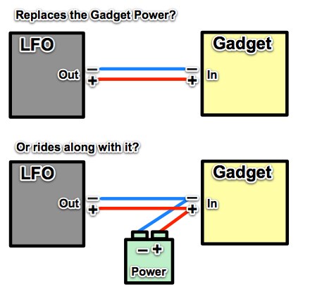
Using the Casper Electronics schematic as a reference, it appears they are jacking into the existing voltage +/- on the Speak and Spell. So, does this mean that when using an LFO (555 based for example) that the LFO becomes the new power source? Or just rides along with the old one?
I'm graphical minded so I whipped up a quickie image in Skitch:
 |
|
|
Back to top
|
|
 |
Danno Gee Ray

Joined: Sep 25, 2005
Posts: 1351
Location: Telford, PA USA
|
| Posted: Fri Mar 12, 2010 5:55 pm Post subject:
|
|
|
| Rides along with it (parellel). |
|
|
Back to top
|
|
|
alienmeatsack
Joined: Mar 04, 2010
Posts: 137
Location: Oklahoma
|
| Posted: Sun Mar 14, 2010 3:00 am Post subject:
|
|
|
Danno, thank you.
I've been doing tons of LFO research online and I found literally dozens of people's own interpretation of how it should be designed and not a single explanation to certain "secrets" aka how does it interface with an existing circuit.
I was having the hardest time trying to figure out how in the heck to get a 9V battery based LFO that puts -maybe- 1-2V out at output end, to work on an existing circuit that runs off 6+ V. Turns out, I don't. Instead I'm just adding it in as a "modulator" or whatever.
Today earlier, I actually breadboarded a 555 based simple LFO and burnt up 3 LEDs trying to figure out what the heck I was doing wrong. They smell pretty bad when that happens and the pos+ side ends up separated. I was holding the entire positive part of one LED earlier and thinking "This is probably not a good thing." 
Now I know I was powering the LFO, thinking it was going to then power the circuit it was connected to.
Since I'm new to all this stuff, I don't always know the right words to search for, or the right methods to do things. I just have the passion.
Today, well, later today, i am going to get out my LFO breadboard and see if I cant get it connected right to my source device again. In this case, it's an APC, so if it dies, I rebuild it.
Woot.
_________________
My Circuit Bending Site (Coming Soon)
My Circuit Bending Blog |
|
|
Back to top
|
|
|
electri-fire
Joined: Jul 26, 2006
Posts: 536
Location: Dordrecht NL
Audio files: 4
G2 patch files: 4
|
| Posted: Mon Mar 15, 2010 5:15 am Post subject:
Using LFO's in circuitbent instruments |
|
|
There's not really a single proper way of using LFO's.
They can be superimposed on the power voltage, riding along with it. This would be the easiest way, and maybe always leave some voltage available so the circuit doesn't shut of completely and reset (if it does that).
Or you can totally replace the power with the LFO and see what that does.
as can be seen in the Speak&* LFO schematic by Casper Electronics, the output of the LFO is connected to the pin that does pitchbend (pin associated with clock circuit).
http://www.casperelectronics.com/images/finishedpieces/speak-n-spell/Speak-n-Xbending/LFO%20schematic2.jpg
Again, you can add it, or try a total replacement. The latter is more complicated, you may need to remove parts or cut a trace. Also you need to find the range of frequencies that the circuit works with. Frequencies are often above audio rate, like a couple of Mz. Not LFO range really. Especially too high clockrate tends to crash the devices, so you need to limit that.
Clock circuits that use resistor(s) and capacitor(s) (and sometimes also coils, like the SK-1) for timing have these external components between two pins of the circuit, one for clock out, one for clock in. When totally replacing the clock circuit you need to connect to the clock in pin.
The benefit of removing external timing circuitry may be more reliable and deeper pitchbend range.
For an example you might look at SamZen's sk-1 clock replacement.
LFO's at address lines or data lines.
Devices that use memory (ROM's , RAM's) like the Speaks, samplers, like SK-x's Yamaha VSS-30 / 200, all sorts of drum machines and "romplers" retrieve data from the ROM/RAM by sending an address to select the memory location, and use the data to "do it's thing".
LFO's can be used for address and data lines. Some devices have address/data pin function combined (a pin is both input and output, so first the address is sent, next the same pins are read).
. |
|
|
Back to top
|
|
|
alienmeatsack
Joined: Mar 04, 2010
Posts: 137
Location: Oklahoma
|
| Posted: Mon Mar 15, 2010 9:43 am Post subject:
|
|
|
Thanks for the info and insight! I am still learning about all this stuff here. So I am trying to get my hands on and try anything and everything I can.
I will have to look into the LFO stuff more. Someone elsewhere told me what I was trying to do was actually more of a VCO.
I'm trying to make small simple circuits I can add to my circuit bends, new circuit projects, etc. Anything to give me more options for changing the sound output of my gadgets is a good thing.
And, I'm slowly working on trying to build a synth or something that does synth like things. Possibly something bass specific for a DnB project I have wanted to work on for years.
_________________
My Circuit Bending Site (Coming Soon)
My Circuit Bending Blog |
|
|
Back to top
|
|
|
electri-fire
Joined: Jul 26, 2006
Posts: 536
Location: Dordrecht NL
Audio files: 4
G2 patch files: 4
|
| Posted: Mon Mar 15, 2010 12:29 pm Post subject:
|
|
|
[quote="alienmeatsack"]I'm trying to make small simple circuits I can add to my circuit bends, new circuit projects, etc. /.../
And, I'm slowly working on trying to build a synth or something that does synth like things. [quote]
Did you see the Lunetta forum?
http://electro-music.com/forum/forum-160.html |
|
|
Back to top
|
|
|
alienmeatsack
Joined: Mar 04, 2010
Posts: 137
Location: Oklahoma
|
|
|
Back to top
|
|
|
jamiewoody
Joined: May 28, 2010
Posts: 10
Location: western north carolina
|
| Posted: Fri May 28, 2010 10:34 pm Post subject:
|
|
|
apc's (stepped tone generator) are easy to build. just remember the jumpers or it wont work.
i like to design around 555 timers, for ease. for the "lunetta" as someone called it, just put a photo cell where there would otherwise be a potentiometer! or, some use both...
lately i am into the cmos scene! my biggest problem with my schmitt trigger based synth was lack of volume and some noise. any advice for this? should i have used an lm741 op amp as well? how do those hook together best?
i made this one synth with 2 555 timers, separate circuits, connected making one circuit. resistors and caps in the same place. i think the only difference was 2 caps. i found some very low fequencies! i built both this an an APC into one box. the APC has 3 potentiometers and 4 body contacts! so much fun to play! depending on the waveform generated, the body contacts can be played similar to pads! |
|
|
Back to top
|
|
|
|


 Forum index » DIY Hardware and Software » Circuit Bending


 FAQ
 Calendar
 Search
 Memberlist
 Usergroups
 Register
 Profile
 Log in to check your private messages
 Log in
 Chat Room


